The Data set
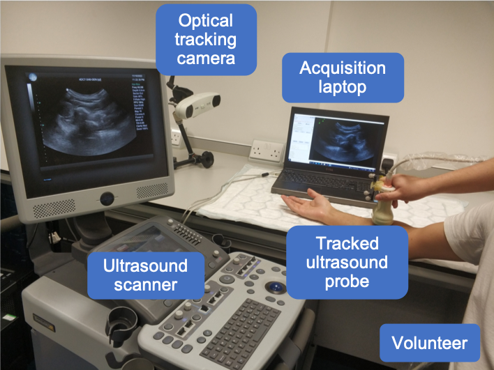
The data in this challenge is acquired from both left and right forearms of 85 volunteers, acquired at University College London, London, U.K, with a racial-, gender-, age-diverse subject cohort. Fig. 3 shows the equipment setting during acquisition. No specific exclusion criteria as long as the participants do not have allergies or skin conditions which may be exacerbated by US gel. All scanned forearms are in good health. The data is randomly split into train, validation, and test sets of 50, 3, and 32 subjects (100, 6, 64 scans; ~164k, ~9k, ~90k frames), respectively.
Images
The 2D US images were acquired using an Ultrasonix machine (BK, Europe) with a curvilinear probe (4DC7-3/40). The acquired US frames were recorded at 20 fps, with an image size of 480×640, without speckle reduction. The frequency was set at 6MHz with a dynamic range of 83 dB, an overall gain of 48% and a depth of 9 cm. Both left and right forearms of volunteers were scanned. For each forearm, the US probe was positioned near the elbow and moved around the fixed contact point. It was first fanned side-to-side along the short axis of the skin-probe interface and then rocked along the long axis in a similar manner. Afterwards, the probe was rotated about 90 degrees, and the fanning and rocking motions were repeated. The dataset contains 170 scans in total, 2 scans associated with each subject, around 1500 frames for each scan.
Labels / Transformations
The position information recorded by the optical tracker (NDI Polaris Vicra, Northern Digital Inc., Canada) will be provided along with the images, which indicates the position of the US probe for each frame in the camera coordinate system, described as homogeneous transformation matrix with respect to reference frame. A calibration matrix will also be provided, denoting the transformation between US image coordinate system and tracker tool coordinate system while these data were acquired. The data is provided temporally calibrated, aligning the timestamps for both transformations from the optical tracker and ultrasound frames from US machine.
An illustration of a scan is shown in Fig. 4.
Train Data Structure (Link to train dataset)
Freehand_US_data_train_2025/
    │
    ├── frames_transfs/
    │   ├── 000/
    │       ├── RH_rotation.h5 # US frames and associated transformations (from tracker tool space to optical camera space) in rotating scan of right forearm, subject 000
    │       └── LH_rotation.h5 # US frames and associated transformations (from tracker tool space to optical camera space) in rotating scan of left forearm, subject 000
    │
    │   ├── 001/
    │       ├── RH_rotation.h5 # US frames and associated transformations (from tracker tool space to optical camera space) in rotating scan of right forearm, subject 001
    │       └── LH_rotation.h5 # US frames and associated transformations (from tracker tool space to optical camera space) in rotating scan of left forearm, subject 001
    │
    │   ├── ...
    │
    │
    ├── landmarks/
    │   ├── landmark_000.h5 # landmarks in scans of subject 000
    │   ├── landmark_001.h5 # landmarks in scans of subject 001
    │   ├── ...
    │
    └── calib_matrix.csv # calibration matrix
- Folder
frames_transfs: contains 50 folders (one subject per folder), each with 2 scans. Each .h5 file corresponds to one scan, storing image and transformation of each frame within this scan. Key-value pairs and name of each .h5 file are explained below.-
frames- All frames in the scan; with a shape of [N,H,W], where N refers to the number of frames in the scan, H and W denote the height and width of a frame. -
tforms- All transformations in the scan; with a shape of [N,4,4], where N is the number of frames in the scan, and the transformation matrix denotes the transformation from tracker tool space to camera space. -
Notations in the name of each .h5 file:
RH: right arm;LH: left arm. For example,RH_rotating.h5denotes a rotating scan on the right forearm.
-
-
Folder
landmarks: contains 50 .h5 files. Each corresponds to one subject, storing coordinates of landmarks for 2 scans of this subject. For each scan, the coordinates are stored in numpy array with a shape of [100,3]. The first column is the index of frame; the second and third columns denote the coordinates of landmarks in the image coordinate system. - Calibration matrix: The calibration matrix was obtained using a pinhead-based method. The
scaling_from_pixel_to_mmandspatial_calibration_from_image_coordinate_system_to_tracking_tool_coordinate_systemare provided in the “calib_matrix.csv”, wherescaling_from_pixel_to_mmis the scale between image coordinate system (in pixel) and image coordinate system (in mm), andspatial_calibration_from_image_coordinate_system_to_tracking_tool_coordinate_systemis the rigid transformation between image coordinate system (in mm) to tracking tool coordinate system. Please refer to an example where this calibration matrix is read and used in the baseline code here.
- Additional training and validation data (optional) come from previous challenge (TUS-REC2024), on the same cohort but with different scanning protocols. The patient IDs are consistent across datasets of TUS-REC2024 and TUS-REC2025 to ensure participants can properly account for data distribution when incorporating TUS-REC2024 data.
Validation Data
The validation data is available here, which has the same structure as the test data. The data folder structure is as follows. Details can be found in the zenodo page. The validation data is different from the training data in that: 1) the image and transformation for each scan are stored separately in two folders; 2) the added file dataset_keys.h5 contains the paths to all scans in the dataset.
Freehand_US_data_val_2025/
    │
    ├── frames/
    │   ├── 050/
    │       ├── RH_rotation.h5 # US frames in rotating scan of right forearm, subject 050
    │       └── LH_rotation.h5 # US frames in rotating scan of left forearm, subject 050
    │
    │   ├── 051/
    │       ├── RH_rotation.h5 # US frames in rotating scan of right forearm, subject 051
    │       └── LH_rotation.h5 # US frames in rotating scan of left forearm, subject 051
    │
    │   ├── ...
    │
    │
    ├── transfs/
    │   ├── 050/
    │       ├── RH_rotation.h5 # transformations (from tracker tool space to optical camera space) in rotating scan of right forearm, subject 050
    │       └── LH_rotation.h5 # transformations (from tracker tool space to optical camera space) in rotating scan of left forearm, subject 050
    │
    │   ├── 051/
    │       ├── RH_rotation.h5 # transformations (from tracker tool space to optical camera space) in rotating scan of right forearm, subject 051
    │       └── LH_rotation.h5 # transformations (from tracker tool space to optical camera space) in rotating scan of left forearm, subject 051
    │
    │   ├── ...
    │
    │
    ├── landmarks/
    │   ├── landmark_050.h5 # landmark coordinates in scans of subject 050
    │   ├── landmark_051.h5 # landmark coordinates in scans of subject 051
    │   ├── ...
    │
    ├── calib_matrix.csv # calibration matrix
    └── dataset_keys.h5 # contains paths to all scans in the dataset